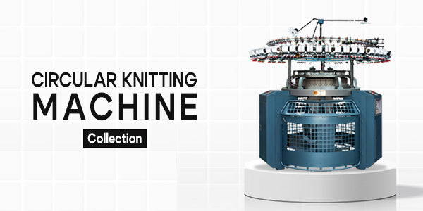
Toprated
Vendor
Example product title
Vendor
Example product title
Vendor
Example product title
Vendor
Example product title
Vendor
Example product title
Vendor
Example product title
Testimonials

Ajay
Great Company & Excellent owner ! Good luck for all future endeavours.
Sharma Kumkum
Ramana International is the best place to buy embroidery machines. Their products are of the highest quality, and their customer service is fantastic. I would highly recommend them to anyone in the textile industry.
Devendra Sharma
Very excellent service and educated staff 👍 I would refer all everyone must buy all knitting and weaving and automatic cutting machine and spreading Machine and sewing & perforation, (3in1), etc machine from Ramana Machine
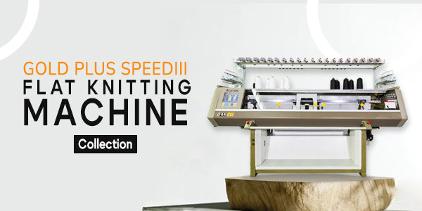
Bestseller
Vendor
Example product title
Vendor
Example product title
Vendor
Example product title
Vendor
Example product title
Vendor
Example product title
Vendor
Example product title


JGR232 SPINNING MACHINE
Couldn't load pickup availability
Description
MAIN TECHNICAL PARAMETER
|
Machine type |
JGR232 |
|
Spindles |
<600 |
|
Rotor speed |
50000 - 120000 r/min |
|
Suitable tex |
83.2 - 16.2tex (7 - 40 Ne) |
|
Density of cotton feeding |
3200-5200tex |
|
Yarn guiding speed |
55 - 200m/min |
|
Splitable roll speed |
6000 - 10000r/min |
|
Twisting degree |
220 - 2250T/M |
|
Suitable fiber length |
< 40 mm |
|
Can bobbing (external diameter x length) |
450X900mm |
|
Spindle Space |
230mm |
|
Rotor diameter (condensed siot) |
31mm, 33mm, 36mm, 40mm |
|
Take - up tube (inner diameter x length) |
54/42X170mm/Straight tube 54/42X170mm |
|
Take - up specs (diameter x length) |
300X150mm |
|
Loaded weight |
<4.5kg |
|
Pressure in rotor cavity |
>6000Pa |
|
Tension stretching time |
0.90 - 1.5time |
MAIN FEATURES
New Generation Optimized Spinning Box
The new generation spinning box ensures stable yarn quality through its integral turning design, which is suitable for producing yarns of varying gauges. The stable negative spinning pressure enhances yarn quality and process stability, making it more competitive. The structure is designed for easy maintenance with reduced labor intensity, allowing quick replacement of spinning components without tools. This ergonomic design simplifies disassembly, cleaning, and maintenance, addressing labor shortages effectively.
Tray Type Rotor Structure Transmission System
The tray-type rotor structure improves efficiency and speed. The imported rotary cup used in the system operates 10%-20% faster than traditional bearing-type rotors, increasing production efficiency.
New Computer Yarn Forming System
This advanced system uses an electronic traverse mechanism, allowing for adjustable winding angles through a computer screen. It helps reduce or eliminate the chrysanthemum core of cone yarn, ensuring proper winding sequence. The mechanism can independently control the left and right sides, with hydraulic damping used in the creel. The system guarantees proper yarn formation and subsequent annealing. The maximum roll diameter is 320mm, and the weight can reach up to 4.5kg.
Improved Yarn Connecting Method
The system uses a stepper motor to optimize the connecting quality. The semi-automatic connection system can set process data such as feeding amount and time according to different yarn types, ensuring reliable joints. When equipped with an air coil compensator, the negative pressure compensator stores surplus yarn, ensuring high-quality coiling and a perfect roll quality.
Rotor Design
The steel rotating cup offers high efficiency, wear resistance, long service life, and stable spinning quality. It reduces the breakage rate and increases the release strength. The rotor and upper fiber channel can be quickly changed without tools.
False Twist Plate
Various rack sizes are available to meet different raw yarn requirements. The plates are made of high-quality, wear-resistant materials for long-term use.
High Resistance Twister
The ceramic twister provides excellent wear resistance and a smooth finish. Several models are available for high-twist and low-knit yarn production, with quick device replacements that don't require tools.
Electrical Box Design
The double electrical box design offers sufficient space for installing frequency converters, making electrical installation and maintenance easier. The unique cooling air duct in the electrical box ensures effective cooling of electrical components, improving overall stability.
Automatic Doffing Robot
An optional automatic doffing robot can be selected to reduce labor intensity significantly, facilitating smoother operation through man-machine communication.
Installation Requirements
· The distance from the low-voltage distribution cabinet to the machine should not exceed 100 meters.
· Required cable specifications: yellow, green, red, blue, yellow/green, copper core.
· Basic installation: the longitudinal height difference from front to rear should not exceed 20mm, and the transverse height difference should be no less than 10mm.
· The installation ground must be concrete, solid, smooth, and at least 180mm thick.
· A minimum clearance of 1500mm from the machine to walls or obstacles is required (excluding strips).
· A minimum clearance of 1500mm from the machine head and tail to walls or obstacles is required.
